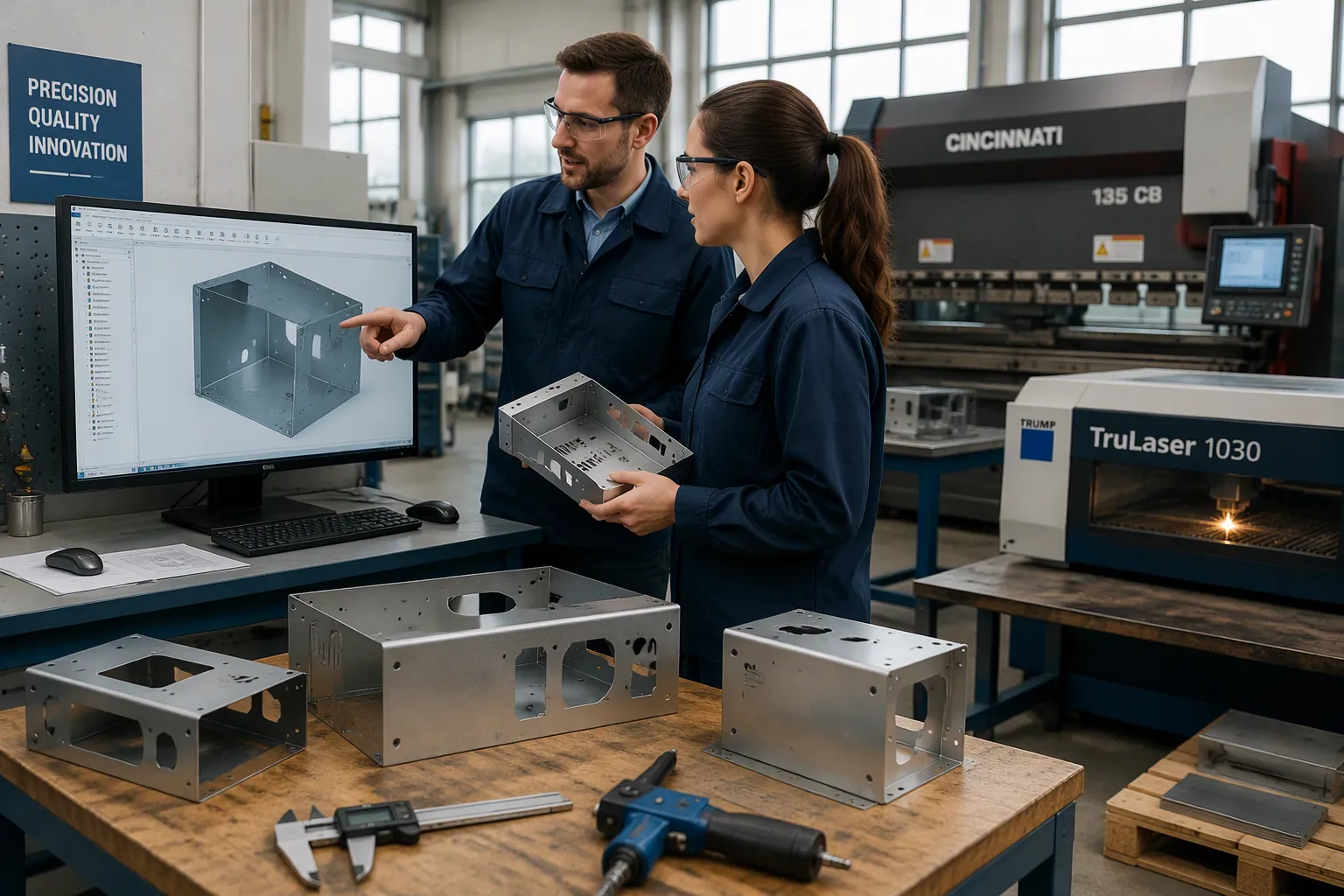
This guide walks you through the essential steps for designing and fabricating custom sheet metal machine housings and equipment enclosures. You will define requirements, select material and thickness, design structure, plan thermal management and sealing, choose finishing, and validate DFM and cost. Whether your project calls for an aluminum sheet metal housing or another alloy, follow these steps in order. This sequence prevents rework and keeps total cost under control.
Key Takeaways
- Define your housing requirements first. This step saves time and money.
- Involve your fabricator early. Early reviews catch problems when fixes are cheap.
- Document IP ratings, loads, and finishes in your RFQ. Clear documents get accurate quotes.
Define Requirements Before You Draw
You save money and time when you lock down requirements before any CAD work begins. Every later decision—alloy, thickness, finish—flows from this foundation.
Operating Environment and IP Target
Start with the real-world hazards your housing will face. Indoor dust, outdoor rain, and high-pressure washdown demand very different ingress protection levels. Match the IP rating to the actual hazard, not to the highest number you can find.
| Environment | Typical IP Rating(s) | Representative Housing |
|---|---|---|
| Industrial indoor (dry/dusty) | IP54 / IP65 | HMI bezels, junction boxes |
| Outdoor (sheltered/exposed) | IP65 / IP66 / IP67 | Control cabinets, sensors |
| Washdown (food, beverage, pharma) | IP69K | Stainless-steel housings |
| Submersion / flood zones | IP68 | Submerged pump controls |
Each digit in an IP rating represents a separate laboratory test. An IP69K device survives a high-pressure hose washdown that an IP67 device would fail. Match the rating to the real-world hazard.
Load, Mounting, and Access Needs
Quantify static and dynamic loads early. Back-panel deflection should stay under 1/200 of the unsupported span. Apply a dynamic factor of 2× for indoor stationary units, 3× for outdoor or pole-mounted units, and 4× or more for vehicle-mounted or seismic-zone installations. Choose mounting hardware by weight: self-tapping screws below 30 lbs, through-bolted backing plates or weld nuts from 30 to 150 lbs, and structural weld nuts above 150 lbs. Plan door swing, service clearance, and cable routing at this stage.
Compliance and Documentation Checklist
Confirm which certification ecosystem applies to your market. IEC markets typically require CE marking, technical files, and test reports. North American markets expect UL Listing or Recognized status, often under UL 508A for assembled panels and UL 50E for the enclosure itself. Build a documentation package that includes a bill of materials with flammability ratings, enclosure drawings with tolerances, assembly procedures, wiring diagrams, and a risk analysis. Supplier certificates for gaskets, coatings, and safety-critical components belong in the same file.
Select Material and Thickness
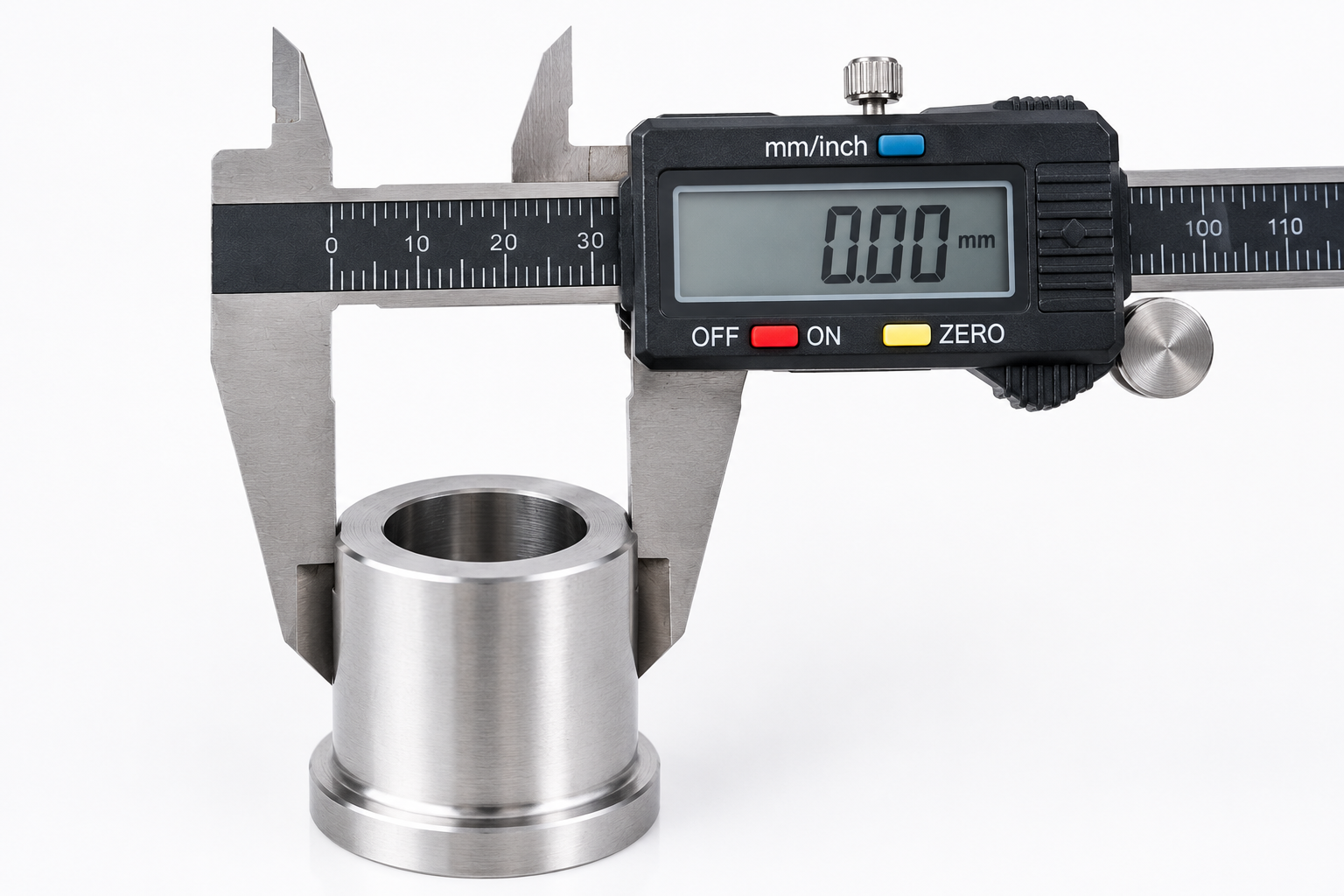
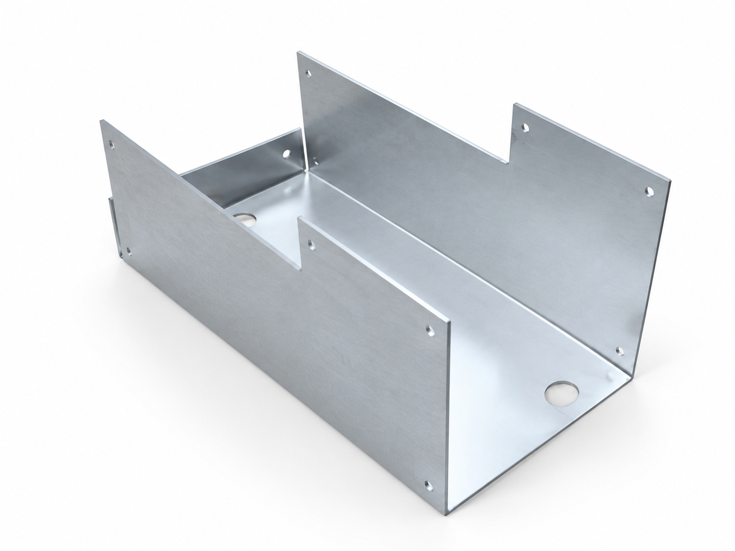
Material and thickness decisions set the strength, weight, corrosion resistance, and cost of your housing. You make these choices once, and every downstream step—bending, welding, finishing—inherits them. Treat this stage as a paired decision: the alloy and the gauge work together, and neither one stands alone.
Alloy Comparison: Cold-Rolled Steel, Stainless, and Aluminum Sheet Metal Housing Options
Three alloy families cover most machine housing work: cold-rolled steel, stainless steel, and aluminum. Each brings a distinct balance of strength, corrosion resistance, formability, and price.
Cold-rolled steel offers high strength at low cost. It forms and welds easily, which makes it a workhorse for industrial control panels, electrical cabinets, and rack enclosures. Bare cold-rolled steel rusts quickly, so it always needs a protective coating. Galvanized steel extends the same family with a zinc layer that improves corrosion resistance for outdoor boxes and general industrial panels.
Stainless steel brings corrosion and heat resistance to the table. Grade 304 handles most indoor and outdoor industrial conditions. Grade 316 adds molybdenum for chloride-rich settings such as salt spray, chemical processing, and washdown areas. Stainless costs more per kilogram than the other two families, and it work-hardens during forming, so you plan bend sequences with care.
Aluminum weighs about one third as much as steel and resists corrosion naturally. Grade 5052 delivers excellent formability and marine-grade corrosion resistance. Grade 6061-T6 offers higher strength for structural panels and machined features. An aluminum sheet metal housing suits electronics, telecom equipment, EV charging stations, and any application where weight matters.
The table below compares representative mechanical properties and material cost across the common grades.
| Material | Yield Strength (MPa) | Tensile Strength (MPa) | Cost (USD/kg) |
|---|---|---|---|
| Stainless Steel 304 | 170–310 | 480–620 | 4–8 |
| Stainless Steel 316 | — | — | 6–12 |
| Aluminum 5052-H32 | 160 | 215 | 2–5 |
| Aluminum 6061-T6 | 241–276 | 276–310 | 2–5 |
| Steel ASTM A36 (reference) | 250 | 400–550 | Low |
Read the numbers with care. Aluminum 6061-T6 reaches yield strength close to mild steel at roughly one third the density. Stainless 304 wins on corrosion resistance and elongation, and its price reflects that. Cold-rolled steel remains the cost leader for strength per dollar when a coating protects it.
Thickness Trade-Offs: Strength vs. Weight vs. Cost
Thickness drives stiffness far more than strength alone suggests. A panel's resistance to bending scales with the cube of its thickness, so a small gauge increase delivers a large stiffness gain. That relationship cuts both ways: doubling thickness multiplies panel weight and material consumption.
Typical thickness ranges cluster by material and application. Aluminum housings usually run 1.0 mm to 3.0 mm. Cold-rolled steel enclosures run 1.2 mm to 2.5 mm. Stainless steel housings run 1.0 mm to 2.0 mm. Small electronic housings stay near the lower end. Large cabinets and high-vibration systems move toward thicker sheets.
Six factors shape the thickness decision, and you weigh them together:
- Stiffness: A thicker panel resists bending and vibration better than a thin one. This matters when the enclosure supports heavy components such as transformers or power supplies.
- Weight: Doubling thickness significantly increases enclosure weight, especially on large panels. Wall mounting, shipping, and installation all feel the difference.
- Design balance: Flanges, ribs, and folded edges add rigidity without adding material thickness. You gain strength through geometry rather than heavier sheet.
- Material cost: Thicker sheets consume more raw material. Even small thickness increases raise cost because total surface area multiplies material usage.
- Fabrication cost: Thicker material demands higher cutting power, stronger press brake tonnage, and sometimes extra machining steps.
- Shipping cost: Heavier enclosures require more packaging and more transportation weight.
Thickness also controls bend radius, tooling, and final part cost. Watch the gauge convention: gauge numbers run backward, so a higher gauge means a thinner sheet. The same gauge number also yields different actual thicknesses for steel versus aluminum. Confirm the decimal thickness on the drawing rather than the gauge number alone.
The most common cause of first-round prototype failure is not insufficient material strength. It is a mismatch between thickness and bend radius, holes too small or too close to edges and bend lines, and fit tolerances consumed after finishing.
Thin material bends easily but tends to bulge, deform, or vibrate. Thick material stays stable but needs larger bend radii, higher press capacity, and higher processing cost. From a DFM perspective, you check load requirements, bend radius, part size, hole diameter, hole-to-edge distance, fastener specifications, welding heat input, and coating thickness at the same time.
Matching Material to Application
Application requirements point to a clear starting material in most projects. Use the table below as a first-pass selector, then refine with load calculations and environment data.
| Application | Recommended Material | Key Property | Thickness Note |
|---|---|---|---|
| Food processing | Stainless steel 304/316 | Corrosion and chemical resistance | Sheet range ~0.5–6 mm |
| Medical | Stainless steel 304/316 | Corrosion and heat resistance | Sheet range ~0.5–6 mm |
| Outdoor | Galvanized steel or Aluminum 5052 | Zinc coating or natural corrosion resistance | Sheet range ~0.5–6 mm |
| Heavy industrial | Carbon steel (cold rolled) | Strength, low cost, weldability | Heavy covers 2 mm and up |
Food processing and medical equipment lean on stainless steel for cleanability and chemical resistance. Grade 316/316L handles chloride-rich washdown and sterilization cycles. Outdoor installations favor galvanized steel for budget-driven projects and aluminum 5052 where weight and salt exposure dominate. Heavy industrial frames and covers use cold-rolled carbon steel for strength per dollar, with a coating to stop rust.
Keep the sheet-versus-plate boundary in mind. Foil sits below 0.5 mm and serves shielding and packaging. Sheet spans roughly 0.5 mm to 6 mm and covers enclosures, brackets, and panels. Plate runs above 6 mm and belongs to machine bases and structural parts. Most machine housings live entirely in the sheet range.
Weight-sensitive designs often settle on an aluminum sheet metal housing with folded flanges for stiffness. Corrosive environments push toward stainless. High-volume cost targets pull toward coated cold-rolled steel. When two materials sit close on performance, compare total finished cost—material, fabrication, and finishing—rather than raw sheet price alone.
Design the Structural Features
Structural features turn a flat blank into a rigid, serviceable housing. Bend rules, fastener choices, and access design all interact, so you plan them together.
Bend Radii and Flange Rules
A bend radius that is too tight cracks the material. The table below gives the minimum inside radius for each common alloy.
| Material | Minimum Inside Bend Radius |
|---|---|
| Mild steel | 1.5× thickness |
| Aluminum 3003-O | 0.5× thickness |
| Aluminum 6061-T6 | 1× to 3× thickness |
| Stainless steel | 1× to 2× thickness |
Allow a minimum flange length of 4× material thickness. A shorter flange buckles or tears during bending. A 0.030 in. (0.76 mm) internal radius suits about 95% of parts, and standard tooling covers 0.010 in. to 0.250 in. Keep one radius across all flanges to avoid extra setups. Place holes at least 4× thickness from bend lines, and add bend reliefs where two flanges meet. These rules apply to every alloy, including an aluminum sheet metal housing.
Fastener and Joint Selection
Load fasteners in shear, not tension. Tensile loads peel fasteners out of thin sheet, while shear spreads force across a larger area. Use multiple fasteners per joint, and keep holes away from edges and corners.
| Fastener | Best Use |
|---|---|
| Self-tapping screw | Light covers, access panels |
| Machine screw + PEM nut | Serviceable panels, brackets |
| Blind rivet | Structural seams, vibration |
| Rivet nut | Threaded joints in thin sheet |
| Weld stud | High-load structural brackets |
Tab-and-slot joints carry shear through the material itself, and screws or rivets only clamp. For vibration-prone housings, choose blind rivets and self-clinching fasteners. Fasten parts before finishing to protect coating and torque values.
Access Panels, Doors, and Serviceability
Design service access around the maintenance task. Size doors for the tools and hands that will reach inside, and plan hinge swing and clearance before you fix the layout. Removable panels with captive fasteners speed field service. Group frequently serviced components behind one panel.
Plan Thermal Management and Sealing
Heat and moisture decide whether your housing survives its service life. You plan both together, because a cooling opening and a sealed joint pull in opposite directions.
Passive and Active Cooling Options
Start with passive techniques. Fins, heat sinks, and high-conductivity materials such as aluminum move heat without power or maintenance. An aluminum sheet metal housing naturally spreads heat better than steel. Natural convection vents suit modest loads in clean indoor settings, but they drop ingress protection to roughly IP30.
Active methods remove more heat. Filtered fans cost the least, and they work with IP54 when you specify proper filters. Air-to-air heat exchangers keep the enclosure sealed and suit washdown and outdoor duty. Enclosure air conditioners cool below ambient and hold IP65 or better. Air-to-water exchangers deliver high capacity in plants with tempered water. Vortex tubes need only compressed air, which makes them useful where motors are excluded.
| Environment | Heat Load | Recommended Method |
|---|---|---|
| Clean indoor | Any | Vents, then filtered fans |
| Dusty or oily indoor | Medium to high | Filtered fans or air-to-air exchanger |
| Washdown or outdoor | Any | Air-to-air exchanger |
| Ambient hotter than limit | Any | Air conditioner or air-to-water exchanger |
Gasket Selection and Groove Design
Match the gasket to the rating and the chemistry. Neoprene covers general IP54 duty at the lowest cost. EPDM adds weather, ozone, and UV resistance for outdoor use. Silicone handles extreme temperatures from -65°F to +400°F. Size the groove for 25–30% compression, keep the path continuous, and space fasteners 3–4 inches apart. Recessed grooves that retain the gasket outperform surface-adhesive placement.
Weld Sealing vs. Gasketed Joints
Welded seams give you a permanent, fully sealed joint with no gasket to age. They suit IP67 and washdown housings, and they add labor and distortion risk. Gasketed joints allow service access and field repair. Choose welds for fixed seams and gaskets for doors and removable panels.
Cable Entry and Pressure Equalization
IP67 achievement typically requires welded or heavily gasketed construction, sealed cable glands, and pressure equalization vents preventing internal vacuum during temperature changes.
Place entries on the bottom or sides, never the top. Match each gland to the cable diameter, install blanking plugs in unused entries, and add strain relief. A 50°C temperature swing creates about 0.18 bar of differential pressure, enough to deform panels and pull water past seals. An ePTFE breather vent passes air while blocking water, so mount it high and shield it from spray.
Choose Surface Finishing
Surface finishing protects your housing and defines its appearance. You choose a finish after you settle the alloy, because the substrate limits your options.
Powder Coating vs. Wet Paint
Powder coating delivers a hard, thick film with strong chip and abrasion resistance. Wet paint applies thinner and suits precision fits and fine details. The table below compares the two.
| Criterion | Powder Coating | Wet Paint |
|---|---|---|
| Film thickness | 2.5–6.0 mils | 0.5–2.0 mils |
| Durability | Hard, chip-resistant | Softer; needs multi-coat systems |
| Cost at volume | Lower per part on automated lines | Lower setup cost for small runs |
| Field repair | Liquid touch-up only | Sand and recoat on site |
Powder coating adds roughly 0.003–0.004 in. per side, so oversize tight-tolerance holes before coating. Choose powder for production runs and industrial duty. Choose wet paint for oversized parts, heat-sensitive assemblies, and on-site touch-ups.
Plating, Conversion Coatings, and Anodizing
Plating adds a metallic layer for corrosion protection and conductivity. Zinc plating with chromate suits cost-sensitive carbon steel brackets. Black oxide forms a conductive oxide layer on steel and barely changes dimensions. Passivation removes free iron and gives stainless steel greater rust protection than black oxide.
Anodizing builds an insulating oxide layer on aluminum. Type II anodizing offers good aesthetics at moderate cost. Type III hardcoat anodizing resists wear and abrasion. Conversion coatings such as Alodine cost less and retain conductivity, which makes them a common primer for an aluminum sheet metal housing.
Finish Selection by Environment
Match the finish to the threat. Dry indoor settings often need no finish beyond light oil or black oxide. Outdoor duty calls for powder coating, painted primer systems, or Type II/III anodizing with verified UV stability. Marine and coastal sites favor passivated 316 stainless steel or marine-grade powder coat, verified with salt spray testing. Chemical exposure demands electropolished stainless steel or specialized coatings, selected against the specific chemical, concentration, and temperature.
Validate DFM and Cost
You have a design, a material, and a finish. Now you prove the design can be built at a sensible price. DFM validation and cost modeling work as a pair. A design that ignores manufacturing reality costs more than the drawing suggests. A cost estimate that ignores design complexity misleads your budget. Run both checks before you release the design.
Design-for-Manufacturability Checks
DFM review asks one question: can a fabricator build this part reliably at the quoted price? You answer that question by walking through the design feature by feature. Start with simplicity. Complex geometries and overly tight tolerances raise error risk and demand specialized tooling. Simplifying the design cuts production time and cost without sacrificing quality.
Tolerance strategy deserves its own pass. Specify tolerances that match the process. Overly tight tolerances demand precision equipment and extra inspection, and they drive up cost. Proper tolerance optimization keeps parts fabricable and consistent. Apply a ±.010 in. default tolerance across the drawing, then tighten only the dimensions that function requires.
The table below lists the core DFM guidelines and the cost or issue each one avoids.
| DFM Guideline | Recommendation | Cost / Issue Avoided |
|---|---|---|
| Tolerance optimization | Maximize tolerances on punched parts; avoid unnecessarily tight fits between punch and die | Tighter tolerances accelerate tool wear and raise cost |
| Material orientation | Align grain/roll direction close to perpendicular to bend lines; nest parts efficiently on the sheet | Prevents cracking or weakness at bends (especially 6061-T6); reduces scrap and material cost |
| Bend allowance | Accurately relate 2D blank geometry to finished 3D bent geometry; confirm with your manufacturer | Prevents tolerance errors for features spanning bends |
| Minimum bend radius | Respect material and tooling limits on bend radius | Avoids material yield failure and part rejection |
| Slots, notches, tabs | Slots wider than material thickness; slots at least 2× thickness from edges and 4× thickness from bends; notches at least 1× thickness wide; tabs at least 2× thickness wide | Avoids tearing and deformation near cuts and bends |
| Stiffeners (beads, emboss, ribs, hems) | Emboss depth no more than 3× material thickness; account for thinning at beads; use rolled or teardrop hems on brittle materials | Prevents tearing, fracture, and splitting during forming |
| Finishing and assembly | Account for coating dimensional change and uncoated hold points; design self-locating parts; prefer PEM inserts or rivets over welding where possible | Reduces fixturing, assembly time, and rework cost |
Several recurring mistakes account for most DFM-driven cost overruns. Check your design against this list before you send it out.
- Unnecessarily tight tolerances throughout. Apply a ±.010 in. standard default tolerance and specify tighter tolerances only where function requires it.
- Sharp inside corners on formed parts. Specify a .030 in. or larger inside bend radius unless zero radius is functionally required.
- Holes too close to bend lines. Maintain at least 2.5× material thickness plus bend radius from hole edge to bend centerline.
- Weld joints in inaccessible locations. Design parts so weld joints are accessible from outside the assembly.
- Many different fastener types in one assembly. Standardize on two or three fastener types unless function requires variety.
- Specifying premium material without functional justification. Default to common alloys such as 6061-T6 aluminum, 304 stainless, or cold-rolled steel unless performance demands otherwise.
- Features requiring extensive masking during coating. Specify post-coating drilling and tapping, or redesign to minimize masked features.
Two deeper mistakes hide inside otherwise clean drawings. Designing sheet metal like machined plate ignores the stretching and compression that forming causes. Choosing material on strength or cost alone can produce a part that cracks, warps, or fights the tooling. Balance strength, formability, and environment together.
Finishing deserves early attention in the DFM pass. Coatings often highlight surface flaws rather than hide them, so define cosmetic requirements before production. Coating thickness also changes fits.
Coating buildup of even a few thousandths of an inch at edges, corners, or cutouts can make a precisely sized hole too tight after coating and cause mating surfaces to misalign. Coatings also tend to highlight rather than hide surface flaws, and specialty or non-standard finishes can extend timelines by weeks. When such issues surface after production starts, parts may need rework, scrapping, or remaking—wasting material and machine time—while new programming, updated drawings, and re-sequenced operations compound delays and can trigger rush fees.
The highest-leverage DFM step costs nothing: involve your fabricator early. A manufacturability review before release catches issues while changes are still cheap. The same review after production starts turns a drawing change into scrap, rework, and rush fees.
Cost Drivers and Volume Effects
Sheet metal housing cost breaks into five drivers: material, labor, tooling, finishing, and the volume and complexity of the order. Each driver behaves differently as quantities change. You control total cost by understanding which driver dominates at your order size.
| Cost Driver | How It Drives Cost |
|---|---|
| Material | Largest single driver; stainless and copper cost roughly 2.5–4× mild steel. Cost = flat area × thickness × density × price per kg × (1 + scrap rate of 15–35%). In high-volume runs material can reach about 86% of total cost. |
| Labor | Setup and programming time (CNC, laser, brake press) is fixed regardless of batch size and dominates low-volume pricing. Welding adds $1.50–$4.00 per inch; hardware inserts add $0.30–$0.80 each. |
| Tooling | Per-bend setup fees of $15–$45 per unique bend program. Different angles and radii add fixed setup charges even at equal bend counts. |
| Finishing | 25–40% of cost on small enclosures. Powder coating runs $15–$35/m², anodizing $25–$45/m², plating $10–$20/m², and polishing $8–$18/m², plus masking and racking setup. |
| Volume effect | Fixed setup costs spread over more units: 10 pieces cost about 40% of the one-piece unit price; 50–100 pieces cost about 20%. Prototypes carry the highest per-unit cost. |
| Complexity effect | Long or complex cut paths, many holes, tight tolerances (which add 30–60% to bending), and multiple bends all raise cost. Simple outlines are faster and cheaper. These factors compound: thick gauge plus many bends plus tight tolerance equals a much higher cost. |
Read the table as a set of levers. Material dominates at high volume, where scrap rate and nesting efficiency matter most. Labor and tooling dominate at low volume, where setup time is spread over few parts. Finishing holds a surprisingly large share on small enclosures, so a finish change can move the price more than a gauge change.
Volume changes the picture more than any other factor. A single prototype carries the full weight of programming, setup, and tooling. At 10 pieces, the fixed costs spread across ten units and the unit price drops to roughly 40% of the one-piece price. At 50 to 100 pieces, the unit price falls to about 20%. Plan your order quantity around this curve. Ordering a few extra units often costs less per unit than ordering the minimum.
Complexity compounds cost in ways that surprise first-time buyers. Each unique bend angle adds a setup charge. Each tight tolerance adds inspection time. Each long cut path adds machine time. Combine a thick gauge with many bends and tight tolerances, and the cost multiplies rather than adds. A design review that removes one bend angle or relaxes one tolerance band can pay for itself many times over.
Use these drivers to build a cost model before you request quotes. Estimate flat area, thickness, and scrap rate for material. Count unique bends and estimate setup for tooling. Estimate coated area for finishing. Then apply the volume curve. A rough model built this way tells you whether a quote is reasonable and where to focus design changes. It also tells you when an aluminum sheet metal housing earns its higher material price through lower weight, easier forming, or simpler finishing.
Build the RFQ Package
A complete RFQ package gets you comparable quotes and fewer surprises. Assemble the documents before you contact any fabricator.
Drawings, Models, and Specifications
Send a 2D PDF drawing and a matching 3D CAD model in STEP or IGES format. Your fabricator imports the model into CAM software to calculate toolpaths, cycle times, and setup needs. The PDF drawing remains the legal authority for manufacturing. It must carry critical tolerances, surface finishes, thread callouts, and datum structures. Match the revision block on the PDF to the revision level of the CAD file. Out-of-sync revisions are a leading cause of scrapped parts.
State the material precisely: alloy, grade, temper, and thickness. Write "6061-T6 Aluminum, 2.0 mm" instead of "aluminum." Name the applicable GD&T standard and edition, such as ASME Y14.5, on the cover sheet. Flag dimensions that control assembly, alignment, sealing, or access, and state whether they apply before or after finishing. Define welds with standard symbols, including joint locations, sizes, and acceptance criteria. Specify the finish as a system: coating type, color reference such as RAL, gloss, masking, and cosmetic acceptance. For assemblies, attach a bill of materials with part numbers, quantities, and responsibility for purchased components.
| RFQ Element | Information to Provide |
|---|---|
| Material | Specific grade (e.g., Stainless Steel 316L) |
| Thickness | Sheet thickness (e.g., 1.5 mm or 16 GA) |
| CAD | 3D model in STEP or neutral format |
| Drawing | 2D PDF with dimensions, tolerances, notes |
| Bends | Bend radii or manufacturer's standard |
| Welding | Weld locations, type, post-weld finishing |
| Hardware | Part numbers and locations |
| Finish | Type, color code, texture, masking |
Tolerances, Quantities, and Certifications
State quantities separately for prototypes and production runs, and request price breaks at 10, 50, 250, and 1,000 pieces. Place the first article on its own PO line with a flat qualification price. Require a First Article Inspection that measures every drawing dimension before the full batch runs. Ask for a CMM report on complex geometries and compound bends. Request mill test reports to verify material grade and mechanical properties, and state RoHS or REACH compliance needs explicitly. List any ISO, ASTM, or military specifications by name rather than assuming your fabricator knows your industry. Attach lead time per PO line, since first article deliveries typically run longer than production replenishment.
Requirements definition drives every downstream decision, from alloy to finish. Early DFM review with your fabricator remains the highest-leverage cost control step, because it catches manufacturing challenges while fixes stay cheap. Document IP targets, loads, and finish specs in your RFQ to get comparable quotes.
For US customers, we build custom sheet metal housings and equipment enclosures, including laser cutting, bending, welding, and surface finishing. Send your drawings for a quotation and design check.
FAQ
Which material should you choose for an outdoor machine housing?
Choose galvanized steel for budget-driven outdoor projects. Pick aluminum 5052 when weight and salt exposure matter most. Specify stainless steel 316 for coastal or chemical environments.
How thick should your sheet metal housing be?
Start with 1.2–2.5 mm for cold-rolled steel and 1.0–3.0 mm for aluminum. Add flanges and ribs for stiffness before you increase gauge. Confirm decimal thickness on the drawing.
When should you involve your fabricator?
Bring your fabricator into the design before you release drawings. An early DFM review catches bend, tolerance, and finishing issues while changes stay cheap. Late fixes drive scrap and rush fees.
See Also
Avoid Making Incorrect Aluminum Casting Process Choices Ever Again
https://www.xuxiangtaimetal.com
Qingdao Xuxiangtai Machinery