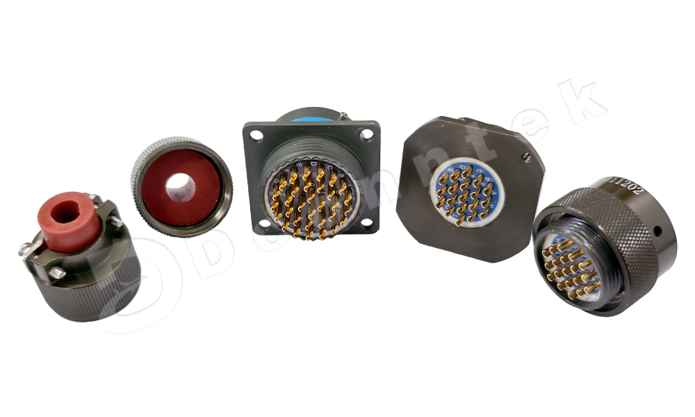
The MIL-C-26482 Series I electrical connector is a classic mid-to-high-end circular connector under the U.S. military standard (MIL-C-26482) system. It features core advantages of "fast and reliable connection, multi-scenario environmental adaptability" and is widely used in the fields of avionics, military equipment, and industrial control. Its design focuses on balancing "connection efficiency" and "basic reliability"—it not only meets the signal/power transmission requirements in harsh scenarios but also controls costs through simplified structures. It is a representative model that "balances cost-effectiveness and performance" in dual military-civilian application fields.
I. Core Positioning: A "High-Efficiency and Reliable Connection Solution" for Mid-to-High-End Scenarios
The original design intention of the MIL-C-26482 Series I is to fill the gap between ordinary industrial connectors and connectors dedicated to extreme environments (such as the MIL-DTL-38999 Series III). It provides a "sufficient and reliable" solution for scenarios that "do not require extreme vibration and corrosion resistance but have clear requirements for connection efficiency, anti-misinsertion, and sealing performance". Its core positioning can be summarized as: "Achieving fast connection with mid-to-high reliability at a moderate cost". Typical applicable scenarios include:
Avionics systems (e.g., aircraft cabin communication modules, navigation auxiliary equipment);
Military vehicle-mounted equipment (e.g., internal communication terminals of armored vehicles, radar auxiliary modules);
High-end industrial control equipment (e.g., main control units of automated production lines, precision testing instruments).
II. Core Technical Features: Design Details Balancing Efficiency and Reliability
1. Connection and Anti-Misinsertion: Fast, Accurate, and Anti-Looseness
(1) Bayonet-Type Connection: Dual Advantages of Efficiency and Reliability
It adopts a bayonet-type fast connection structure, and its core advantages compared with threaded connections are reflected in:
High connection efficiency: Locking can be completed by rotating only a certain angle (usually 90°-120°), which saves more than 60% of operation time compared with ordinary threaded connections. It is suitable for scenarios that require frequent plugging/unplugging or have limited space (e.g., module replacement during equipment maintenance);
Strong locking reliability: Combined with the "pin spiral groove" design, when the three pins on the socket surface slide into the bottom of the spiral groove of the plug connection ring, a clear "click" sound is heard. At the same time, the position of the pins can be visually checked, achieving double confirmation of "proper mating". This avoids poor contact caused by loose connections.
(2) Five-Keyway Anti-Misinsertion: Eliminating the Risk of Incorrect Connection
For scenarios where multiple connectors are used in parallel (e.g., multiple interfaces on an equipment panel), a five-keyway positioning system is adopted—connectors with different core counts and uses are designed with differentiated keyway positions. Mating is only possible when the keyways are fully matched, completely preventing equipment short circuits and module damage caused by misinsertion. This is especially suitable for complex electronic systems (e.g., avionics panels).
2. Termination and Electrical Performance: Core Guarantee for Stable Transmission
(1) Welded Termination: Low Contact Resistance, Suitable for Long-Term Stable Use
The contact termination method is welding, which directly welds and fixes the wire to the contact. Compared with crimping or plug-in termination, its advantages are:
·High connection stability: The metal bonding structure formed by welding can prevent loosening of the contact point caused by vibration, resulting in minimal changes in contact resistance during long-term use;
·Adaptability to complex environments: There is no gap at the welded joint, which can reduce the intrusion of dust and moisture and improve electrical reliability in humid and dusty scenarios.
(2) Key Electrical Parameters: Covering Mid-to-High-End Requirements
|
Electrical Parameter |
Specific Specification |
Advantage Interpretation |
|
Rated Voltage |
300V for regular models, up to 2300V for some models |
Suitable for both low-voltage signals (e.g., control signals) and high-voltage power supplies (e.g., equipment power supply), with wide scenario compatibility |
|
Current Capacity |
16A for size 16 pins, 7.5A for high-density size 20 pins |
Meets the needs of low-to-medium power equipment (e.g., communication modules, sensors); high-density pins are suitable for parallel transmission of multiple signals |
|
Contact Resistance |
≤6mΩ for size 16 pins, ≤15mΩ for size 20 pins |
Extremely low contact resistance reduces signal transmission loss, suitable for high-frequency or weak signals (e.g., sensor detection signals) |
|
Insulation Resistance |
≥5000MΩ |
Excellent insulation performance prevents leakage between contacts or between contacts and the housing, ensuring equipment safety |
III. Environmental Adaptability: Coping with Mid-to-High-Level Harsh Scenarios
Although the MIL-C-26482 Series I is not designed for extreme environments (e.g., deep sea, strong salt spray), its material and structural design enable it to withstand harsh conditions in most industrial and military auxiliary scenarios:
1. Wide Temperature and Humidity Tolerance: Covering All Climatic Scenarios
·Operating Temperature: -55℃ to +125℃. It can work stably in extremely low-temperature environments (e.g., military vehicles in northern battlefields) and high-temperature environments inside equipment (e.g., sealed control boxes). The insulators (thermoplastic materials) do not become brittle, and the seals do not age;
·Relative Humidity: Up to 95% at 40±2℃. Even in humid environments (e.g., ship cabins, industrial workshops during rainy seasons), insulation resistance will not decrease due to moisture.
2. Vibration and Shock Resistance: Suitable for Mobile Equipment Scenarios
It can withstand vibration of 10-2000Hz and 147m/s² (approximately 15g) as well as shock of 490m/s² (approximately 50g). This meets the mechanical environment requirements of military vehicles (e.g., jolting of armored vehicles) and aviation equipment (e.g., vibration of helicopters during low-altitude flight), ensuring uninterrupted signal/power transmission during vibration.
3. Sealing Performance: Two Solutions for Different Needs
Two sealing forms are available according to the sealing requirements of the scenario:
·Cable Gland Sealing: When the pressure difference is 200KPa, the splash rate is ≤460KPa·cm³/s. Suitable for splash-proof and dust-proof scenarios (e.g., external interfaces of equipment);
·Sintered Sealing: When the pressure difference is 100KPa, the leakage rate is ≤0.1KPa·cm²/s. It has better sealing performance and is suitable for humid and oily scenarios (e.g., equipment on industrial production lines).
4. Salt Spray Resistance and Mechanical Life: Ensuring Long-Term Durability
·Salt Spray Resistance: Can withstand a 48-hour salt spray test (in line with U.S. military standard salt spray test specifications), suitable for mild salt spray environments (e.g., industrial equipment in coastal areas);
·Mechanical Life: Maintains stable performance after 500 plug-in cycles, meeting the maintenance plug-in needs of equipment throughout its service life (usually 5-10 years).
IV. Structure and Materials: Balancing Performance and Cost
1. Material Selection for Core Components
|
Component |
Common Materials |
Core Function |
|
Housing |
Aluminum alloy (nickel-plated), zinc alloy |
Aluminum alloy: lightweight (reducing equipment weight) + nickel plating improves corrosion resistance; Zinc alloy: easy to process via die-casting, suitable for complex housing structures |